PLC Program Download to Studio 5000 Emulator
PLC Programming on Emulator
We mentioned the use and installation of Studio 5000 emulators, in our previous article,
You can access this article from the link below.
Now we will talk about how to install the plc program using the studio 5000 emulator.
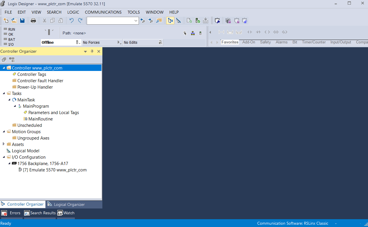
When we open Studio 5000 program, we will see the window as below by default.
We made Studio 5000 settings in our previous article. You can find the project settings in our previous article. You must make the slot and version settings correctly, otherwise an error will occur while loading the program.
For this reason, I pass the creation of a project.
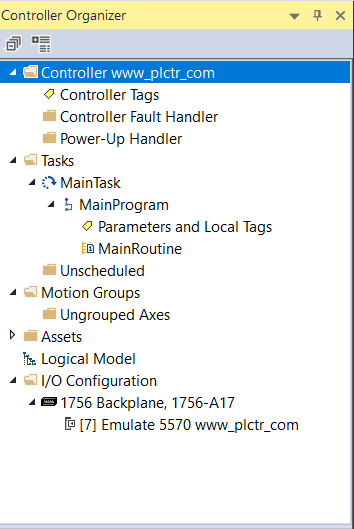
Briefly, if we take a look at the tabs under the controls.
Controller Tags: We can see all the tags we created here.
Tags are the addresses we will use in plc.
On the Controller Fault Handler tab, the programs that will run when the PLC program fails are collected under this folder.
Power-Up Handler, on the other hand, has a similar structure as the controller fault handler, it only works when the PLC is first energized.
So if we think about where these parts will work for us, what can we do,
As plc goes to a fault in controller fault handler section, we can catch the error code.
In the Power-Up handler part, we can transfer data to some values in the PLC with predefined parameters or we can back up all the variables when the first energy is given ..
Our main program is where the Tasks tab is located.
Here we will write our program under MainProgram under MainTask.
Each programmer has his own programming styles. What I prefer, and what makes more sense to me, is the lack of computation or program particles in the MainRoutine section.
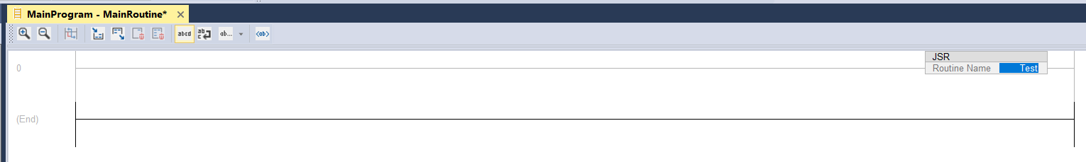
In the MainRoutine section, we will only jump to subprograms and we will use JSR commands only in the task.
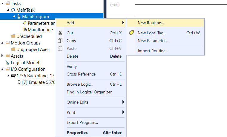
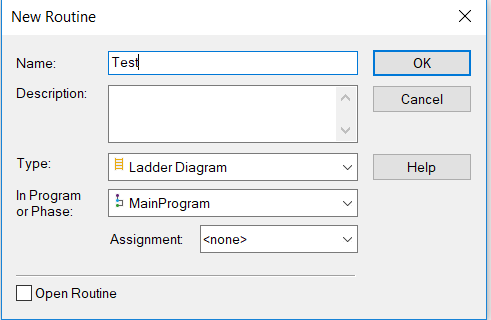
After right clicking on the MainProgram, we will create a new routine with the name TEST using the new Add-New Routine button.
Then, after changing the ladder as below to call the Test program using the JSR command on the MainRoutine page, let’s move on to the Test ladder to write our program.
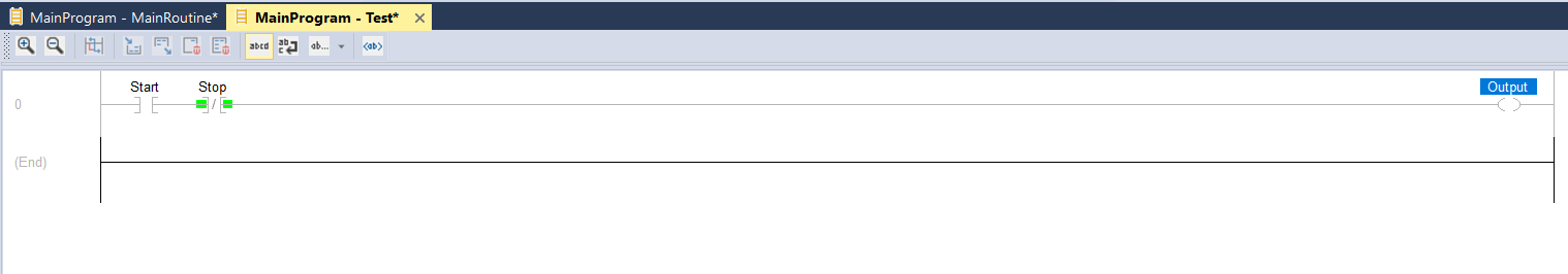
Let’s add the input and output commands using the buttons on the Instruction tab.
![]()
I set the tag names as Start, Stop, and Output.
As long as it is at Start, we have designed a small program with the Output output active.
Right-click on the tag names we have provided and create the tags with Create Tag, then save the program with the SAVE button.
Now it’s time to adjust the settings in the RSLinx program.