how to Create Add-On Instructions in Logix Designer
One of the most powerful newer features of the RSLogix 5000 program is the ability to create Add-On Instructions, It is one of the features that makes the algorithm easy and enjoyable for plc programmers.
How to create and use the add-on instruction Now we will go through an example together.
Let's say we control the AC drive with PLC, which we use common,
To control the AC drive with PLC;
If you do not know how to add modules to the PLC after reading our module addition letter from the link below.
https://www.plctr.com/add-new-module-to-plc-with-logix-designer/
I recommend to read How to Add PowerFlex Driver to PLC chassis in Logix Designer.
Add-On Instruction Motor Control Example
We will use bellow tags in PLC program.
Start: Command required to start the drive
Stop: Command required to stop the drive
Reference: Speed command we will send to the driver
Speed: Speed information we will read from the driver
alarm: Alarm information from the driver
Forward: The driver's decision-making input forward
Reverse: Input required for the drive to reverse
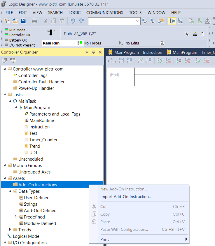
As you can see, the New Add-On Instruction button is gray because I am online to PLC. This means that you can't create an Add-On instruction when you are online with PLC.
Building an Add-On Instruction in RSLogix / Studio 5000
This is one of the major drawbacks of AOIs. However, if planned accordingly, this isn't a problem, but rather a deterrent for anyone to modify your code on a live PLC.
To create a New AOI, right-click on the “Add-On Instructions” Folder in the Controller Organizer and select “New Add-On Instruction”. If this option isn't available, make sure that you are offline; as mentioned above, you won't be able to perform this action online.

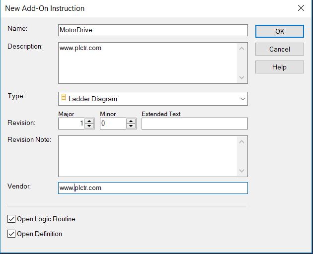
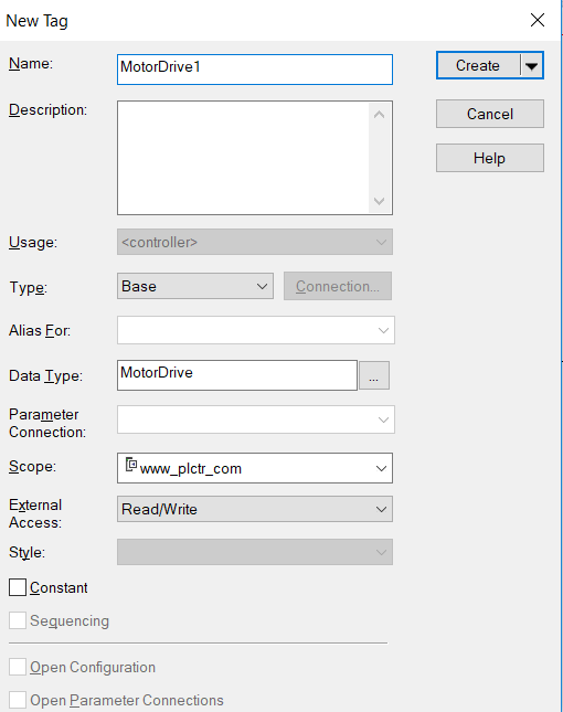
In the new Add On Instruction menu, a window like the one below will appear. In this window, the most important field of AOI such as Name, Description, Revision is the Name field. You cannot change the Name field you have created online later. Since the Name part is usually Add On Instruction, the AOI tag comes before the Name tag. After filling these fields, we create AOI by pressing the OK button.
How do I open the Add-On Instruction Definition Editor dialog box – Parameters tab?
- In the Controller Organizer, expand the Assets folder.
- Right-click Add-On Instructions and choose New Add-On Instruction.
- Fill in the required settings and click OK. The Add-On Instruction Definition dialog box opens.
- Click the Parameters tab.
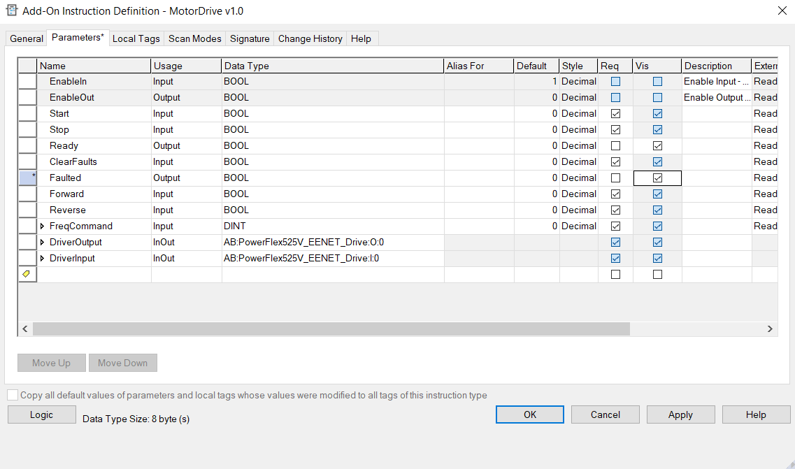
Use the Parameters tab on the Add-on Instruction Editor dialog box to define and configure the parameters of an Add-On Instruction. Add-On Instructions are instructions that you define and add to your project. Once defined in a project, they behave similarly to the controller's built-in instructions.
Add-On Instruction Definition Editor dialog box – Parameters tab settings
The following table describes the settings on the Add-On Instruction Definition Editor dialog box – Parameters tab. Use these settings to define parameters in the Add-On Instruction.
Setting | Description |
Name | The name of the parameter. Names must follow the IEC-1131 Name Standard. The parameter must not have the same name as another parameter or local tag in the same Add-On Instruction definition. The Name box is unavailable for members of InOut parameters. |
Usage | The usage type for the parameter: Input, Output, or InOut.
|
Alias For | The local tag or its member for which you want the parameter to be an alias. For the Add-On Instruction definition, only Input and Output tags can alias local tags. Local tags and InOut tags cannot alias another tag. You can have only one input and one output alias per local tag. Alias For is not available for InOut parameters. |
Data Type | The parameter data type. Input and Output parameters are atomic data types only. During an Add-On Instruction call, Input and Output parameters are passed by value. InOut parameters are atomic or complex data types (that is, structures or arrays). InOut parameters are always passed by reference. Data Type is not available for members of the InOut parameters and the alias parameters. |
Default | The default value that is set when an Add-On Instruction of this type is instantiated. This defines the default values that initially come from the data type. Default values are not applicable to InOut parameters or their members because InOuts are passed by reference. |
Style | The style displayed on the faceplate for this parameter, if it is set to Visible, or the style displayed in the Tag Editor or Data Monitor. The Style box is read-only for members of the InOut parameters. The following settings are available:
|
Req | Determines whether the parameter requires an argument. Req is selected and read-only by default for the InOut parameters because by-reference parameters require an argument. Right-click the Req heading to select or deselect all the rows in the Req column. |
Vis | Determines whether the parameter is visible on the Ladder Diagram and function block diagram instructions when the Add-On Instruction is called. Right-click the Vis heading to select or deselect all the rows in the column. Vis is selected and read-only if Req is selected. The Visible function is not applicable for members of InOut parameters. The Visible configuration may be overridden for Add-On Instruction called in Function Block Diagrams routines if the parameter is not required. Overriding the visibility at the instruction call level does not affect the definition configuration. |
Description | A description for the parameter. If a Parameter does not have a description, the description of the data type is passed through. Because only complex data types have descriptions, only InOut parameters potentially have a description passed through to the parameter. A member of an expanded parameter shows its description, if it has one, on that member in the definition itself. If a member is of another Add-On Instruction type and has its own description defined, which is shown in black text, and passes its description to a member without a description, the description concatenation occurs during pass-through. The description is concatenated with the description from the base tag, which is shown in gray text. |
External Access | Determines whether the tag has Read/Write, Read Only, or no access (None) from external applications such as HMIs. |
Constant | Select the Constant checkbox to prevent executing logic from writing values to the associated tag or parameter. If a logic routine tries to write to a constant tag, the routine will not verify. The Constant checkbox is not available for all tag types. Tip: You can use the Data Monitor dialog box to write values to the parameter. The Value boxes in all other browsers and language editors are disabled when the tag is a Constant tag. Changes made to the values of constant tags are recorded in the Controller Log for future reference. |
Hide and Show Columns | To hide columns in the dialog box, right-click a column header and select Hide Column. To display a hidden column, right-click any column header and select Toggle Column > [column]. |
Editing Modes | An asterisk appears in the first column in the dialog box to indicate that changes have been made to a parameter that has not yet been applied. |
Popup Menu | Right-click a parameter to display a list of operations that you can perform. List of operations. |
Move Up | Moves the selected row or rows of parameters up. Parameters are displayed on the instruction and in the Data Type in the order that you set on the Parameters tab You can also change the parameter order using drag and drop. The EnableIn and EnableOut parameters are at the top of the list and you cannot change their order. |
Move Down | Moves the selected row or rows of parameters down. You can also change the parameter order using drag and drop. |
Copy all default values of parameters and local tags whose values were modified to all tags of this instruction type | Copies all the default values of the parameters, local tags, or members' default values that you have changed to all tag instances of this instruction type. |
Logic | Opens the Logic routine. Logic is not visible if the Add-On Instruction is locked using source protection. |
Data Type Size | Displays the size of the Add-On Instruction data type. The value includes the size of any local tags, even though local tags are not visible when an instance tag of this data type is expanded in the Tag Editor or Data Monitor. However, this value does not include logic size. The size is automatically updated when you apply the instruction, not as you create the parameters and local tags. |
We create the tags we have mentioned above by switching to the Parameters tab in the Add On Instruction we have created. The important thing here is that the Usage field is correct and that the data can be set or read from outside in the Visible column.
If you make it Visible, this tag value will appear in the AOI block you use in the PLC program.
About external access to public and private data
The External Access property setting allows you to specify the level of access (Read Only, Read/Write, or None) external applications and devices have to tags. These external applications and devices include:
- rslinx® Classic and factorytalk® Linx™
- Other Logix controllers
- PanelView
- PLC/SLC controllers
- FactoryTalk Historian
- 3rd party software
The following table describes External Access settings:
External Access setting | Description |
Read/Write | External applications and devices have full access to the tag and can therefore read and change the tag's value. |
Read Only | External applications can read, but cannot change, the tag's value. |
None | External applications cannot read or change the tag's value. |
Important: | The Logix Designer application has full access to all tags, regardless of their External Access setting. |
External access is configured when you create a new tag or data type. After you create a tag, you can modify the tag's External Access setting like you would any other tag attribute.
To write the AOI logic program, right click on AOI and enter the Open Definetion tab.
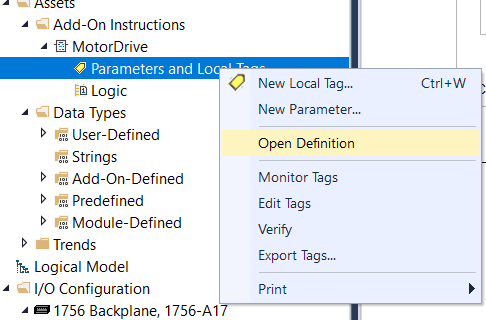
On the logic page, we can write the logic section for engine start by using the tags we have previously created on the parameters page.
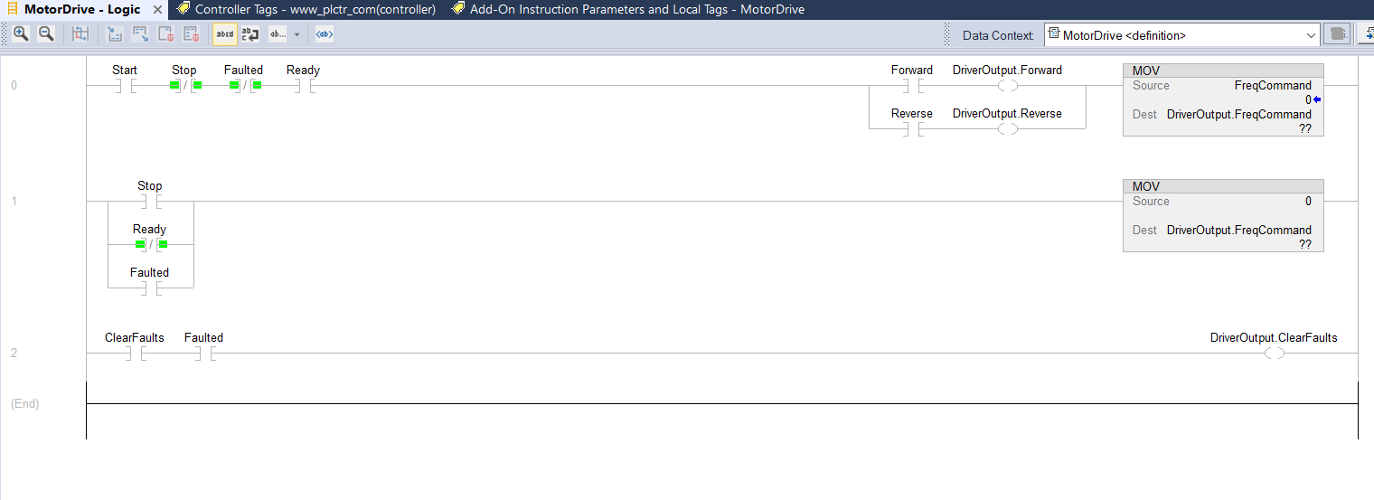
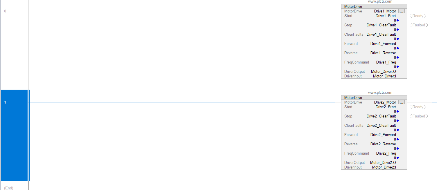
Logic programımızı tamamladıktan sonra PLC programımızda ladder instruction sembollerinin olduğu kısımda oluşturduğumuz AOI görebiliriz.
Oluşturduğunuz Add On Instruction ‘ı diğer instruction'lar gibi kullabilirsiniz.
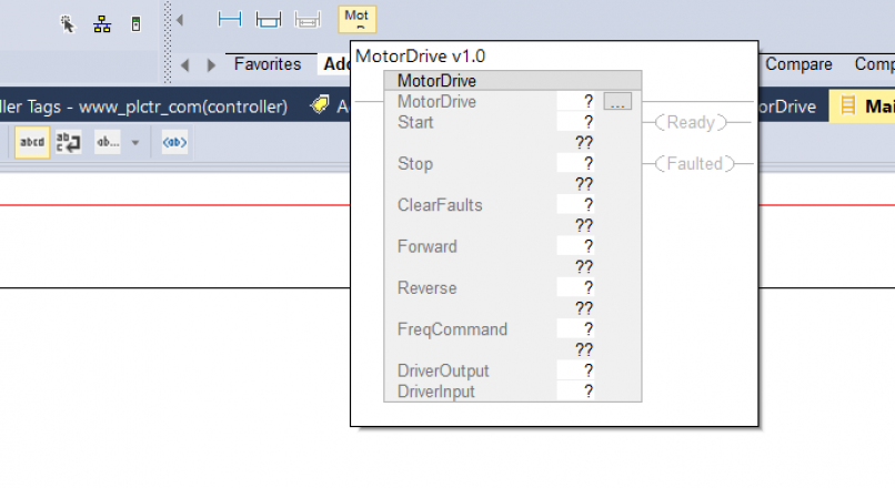
Gördüğünüz üzere visible olan tagler AOI bloğunda görünebilmektedir.AIO ladder ‘a ekledikten sonra tag'leri oluşturup. Kullanabiliriz.
The Add On Instruction blocks will appear on your PLC Ladder page as below.